Geometry
Geometry defines the pack footprint and depth. The generated cell grid, case preview, spacers, keep-outs, and exports all start from this outline.
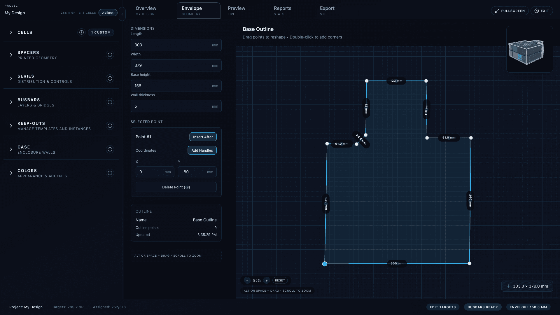
Edit the footprint
- Drag existing points to reshape the closed outline.
- Double-click an edge to insert a new point.
- Select a point to edit coordinates or curve handles.
- Press Delete or Backspace to remove a selected point. The outline keeps a minimum of three points.
- Use the Length and Width controls to rescale the outline numerically in millimeters.
Depth and slot count
Depth
The Depth control maps to the envelope base height. It must fit cell height plus walls, clearance, layer gaps, spacer lips, and optional busbar pockets.
Slots Available
The floating slots panel reports generated cell sites, desired target count, assigned count, unassigned count, and effective parallel when constraints reduce capacity.
Worker updates
In v2, viewer scene computation runs in worker mode. The preview may briefly show Updating preview after geometry changes.
Navigation
- Pan the canvas with Space+drag or Alt+drag.
- Zoom with the mouse wheel or the zoom HUD.
- Use Reset in the zoom HUD to refit the outline.
- Collapse or expand the floating toolbar with T.
Geometry affects everything
Changing the outline after wiring can add, remove, or reorder cell slots. Make major footprint edits before painting series lanes or configuring busbars.
Common checks
- Set the selected cell before trusting slot count; diameter and height determine packing.
- Leave edge clearance and wall thickness for the case instead of drawing the envelope too tight around cells.
- Add known hardware spaces as Case keep-outs before wiring, not as approximate dents in the outline.
- Use Case STL imports for reference-only external geometry such as brackets, frame tubes, or adjacent parts.